The problem
The ranging spec needed three antennas for diversity across orientations. The host MCU had two GPIO lines free and a ranging cadence that could not absorb an I2C round trip every time a switch toggled. Dropping to two antennas lost the diversity. Adding a port expander added a chip and latency. Managing a one of three mux in software left a path where a buggy write connects two antennas to the transceiver at once.
What I did
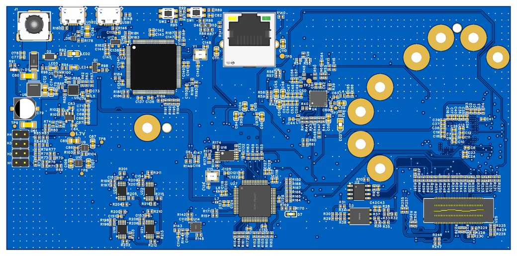
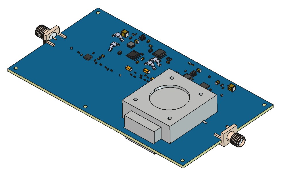
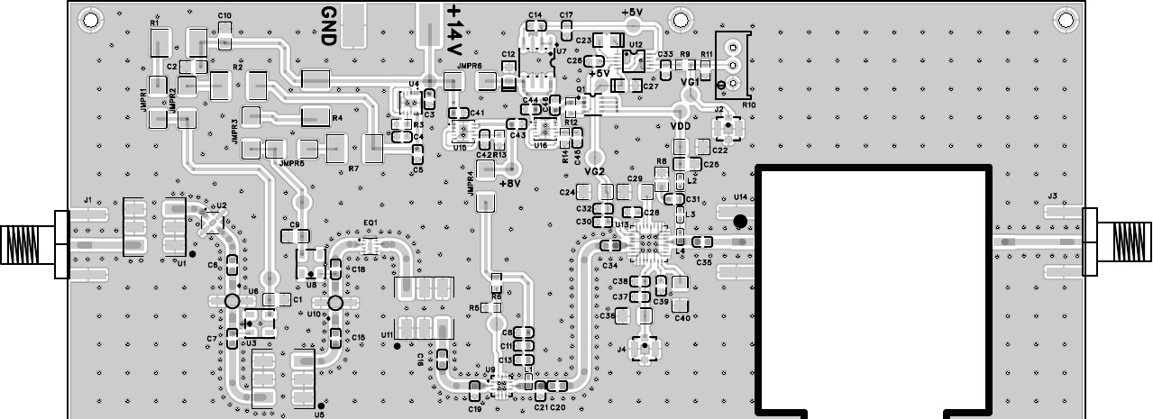
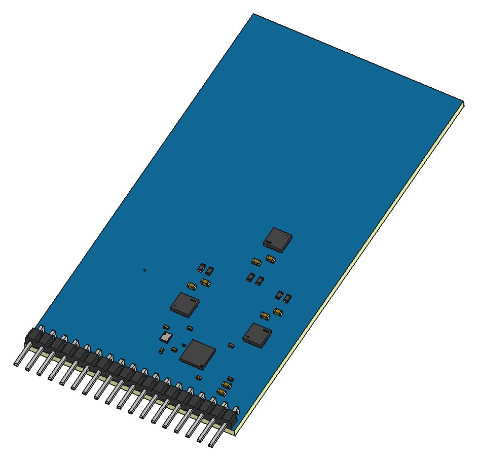
I built the front end as a hardware interlocked one of three selector. Two GPIO lines feed a two gate decoder made from a 74HC02 quad NOR and a 74HC32 quad OR. The truth table maps each 2 bit code to exactly one switch enable and forces the other two off, and the spare fourth code maps to a defined safe state rather than an undefined one. Three matched Analog Devices HMC232ALP4ETR SPDT switches route the chosen antenna into the Qorvo DW3220. The three paths share matched microstrip lengths from the switch outputs so insertion loss and phase stay symmetric, which the ranging algorithm depends on. A companion switch board lets the bring up team measure the switch path on a network analyser before the receiver is on the bench.
Decisions that shaped it
- Interlock in gates, not in a firmware rule. A rule in firmware breaks the first time someone forgets it. The decoder costs about 20 cents.
- A two gate decoder instead of a port expander, so no I2C latency lands in the ranging cadence.
- Three matched SPDTs rather than one SP3T, for part availability, lower loss and phase symmetry.
Result
Three antenna diversity from two pins, with no code path that can connect two antennas at once.