The problem
The client assumed the vendor reference design could be copied onto their board. It cannot. A reference is built around one substrate, one copper weight, one bias current and one land pattern, and changing any of them moves the matching networks. The reference's harmonic filter was also sized for an FCC limit the client did not have to meet, and missed the limit they did. The second harmonic of 2.7 GHz lands inside 5 GHz Wi-Fi territory.
What I did
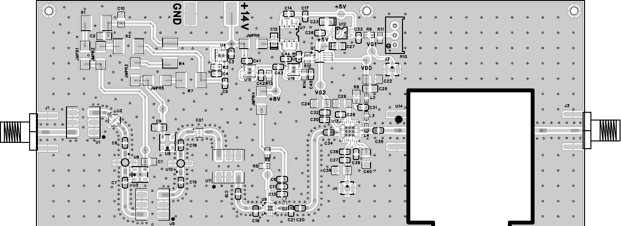
I took the transistor's S-parameters at the bias point closest to the client's quiescent current and built the input match for conjugate match at the source and the output match for the load line at the chosen power, both as L networks on the client's stackup. Then I swept the Rollet k factor and the mu factor across the band and a margin either side.
The first pass had a region above the band where k dipped below one, which is how a working amplifier turns into an oscillator at a frequency nobody is watching. A small loss resistor on the gate bias path absorbed the out of band gain without moving the in band match. A three section low pass on the output puts the second harmonic at 5.4 GHz and the third at 8.1 GHz below the client's limit.
The drain bias tee uses a quarter wave choke with staggered decoupling.
Decisions that shaped it
- Matching against the real substrate and bias point. The reference is a guide, not the design.
- Stability checked across the band, not just at centre. Stability belongs to the network around the transistor, not the transistor.
- Harmonic filter sized to the client's actual regulatory limit.
- Fixed quiescent current with a voltage reference on the gate and current sense on the drain, so the bias does not move the match.
Result
k and mu above one across the sweep, harmonics below the floor, and a Gerber set the client could put on the bench that month.