The problem
A radio with more antennas than radio chains needs a switch fabric between them. A test bench measuring a device through different ports needs the same. The off the shelf answer is an evaluation board with the switch in the middle and not much else, which is expensive per channel and rarely fits a real enclosure. The client also needed to measure the switch path on its own before the receiver it feeds was on the bench, because the integration window left no room for switch debugging.
What I did
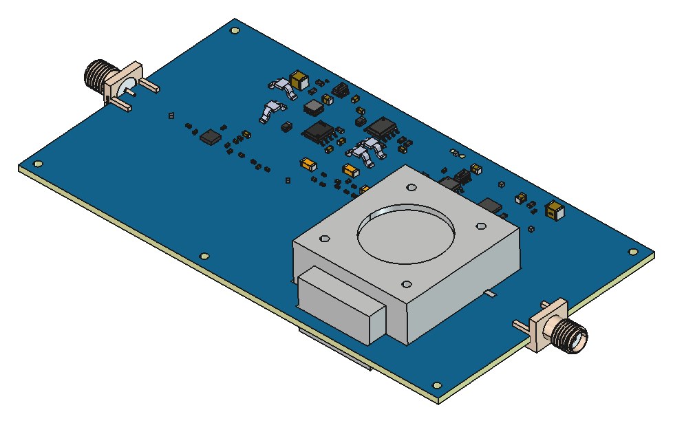
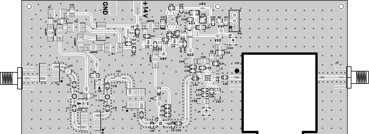
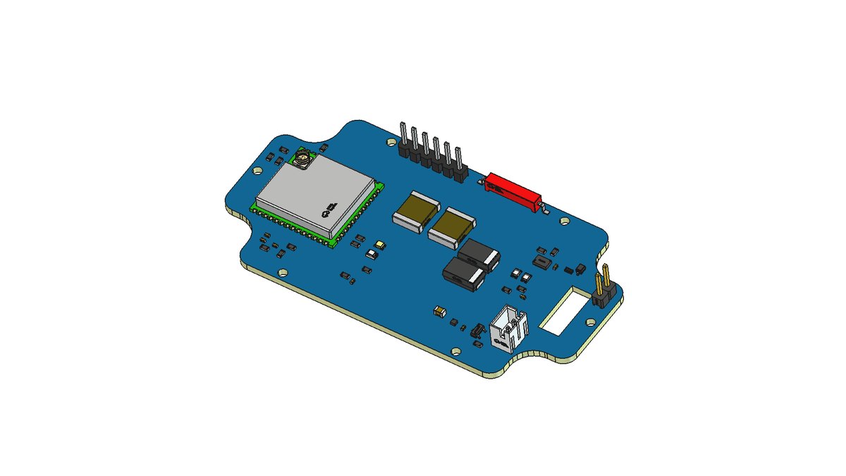
I put the Analog Devices HMC232ALP4ETR SPDT on a board sized for the client's enclosure, with the control lines on a header that a microcontroller or a bench host can drive directly. The RF paths are matched microstrip on a low loss substrate so insertion loss and phase stay symmetric between ports. The same switch design is used in the companion UWB receiver, so the numbers measured here transfer straight to that board.
Decisions that shaped it
- A dedicated two port board so insertion loss, isolation and settling can be measured on a network analyser in isolation.
- Control on a plain header rather than an I2C expander, so there is no software between the host and the switch.
- Matched trace lengths on every path, because a ranging algorithm depends on phase symmetry between antennas.
Result
A cheap, enclosure sized switch board that took the switch characterisation off the receiver's critical path.