The problem
The client had an airframe ready, a flight stack proven against the Pixhawk reference, and an off the shelf controller that did not fit. Connectors on the wrong side, the IMU too close to the motor return currents, a GPS port in a connector shape they had already rejected, and a PWM rail sized for the wrong motor count. Each of those is an annoyance on a desk and a real problem in the air.
What I did
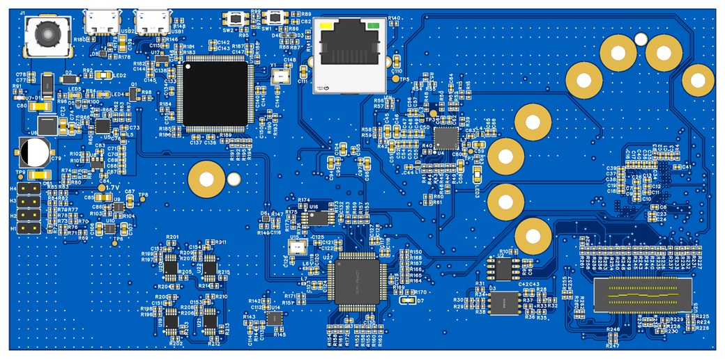
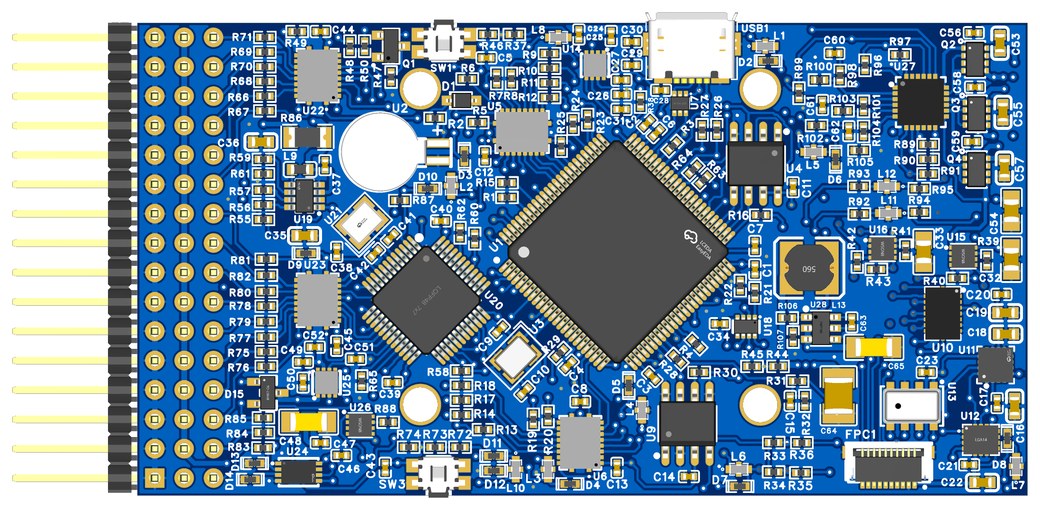
The schematic went onto an STM32H7 with the same bus assignments the Pixhawk firmware expects: SPI for the IMU bus, I2C for the barometer and auxiliary sensors, UART for GPS, telemetry and debug, PWM on the timer channels the firmware drives without a remap. The firmware boots with no source change because it does not know it is on a different board.
The IMU stack sits on its own ground pour with a single tie back to the supply ground at the star point, and the carrier ground does not run under it, so amp scale motor currents never share a path with the IMU bus. The barometer sits on the same island with a vent slot in the case.
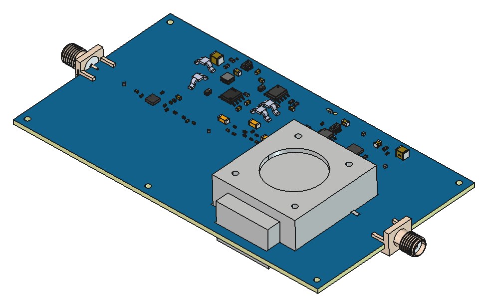
GPS at the front edge, telemetry at the rear, debug on the side, PWM header sized to the motor count, battery voltage and current sense on the input, SD card for the flight log. The 3D model went to the airframe team for a fit check before any Gerber went out.
Decisions that shaped it
- Keep the Pixhawk peripheral map exactly. The value of the reference is that the firmware boots.
- IMU island with a star ground tie, so calibration holds under motor load.
- Connectors placed for the harness the client had already built.
- Vented barometer, because a sealed barometer is a thermometer.
Result
Stock firmware, the client's connectors, and gyro bias that stays where the calibration put it.